Bridge Pin-Outs
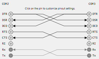
Virtual bridges created by Virtual Serial Port Tools (both local and remote) support custom “wiring” inside a virtual “cable”. You may specify which pins are sending data to which other pins, both on local or remote socket. Below is a default configuration used:
Configuring Pin-Outs
If you are using the Configuration Utility, use Create Local Bridge Window or Create Remote Bridge Window to configure custom wiring.
Local and remote bridge pin-out is configured by settings values of the following properties: IBridgePortDevice.DTR, IBridgePortDevice.DSR, IBridgePortDevice.DCD, IBridgePortDevice.RTS, IBridgePortDevice.CTS and IBridgePortDevice.RI.
Validation
Virtual Serial Port Tools automatically validates the applied configuration and if it is invalid, you get an error from API.
Below is a table that shows you valid configuration for each pin:
| Source Pin | Allowed Destinations |
|---|---|
| DTR (Data Terminal Ready) | DSR, DCD, CTS, RI |
| DSR (Data Set Ready) | DTR, RTS |
| DCD (Data Carrier Detect) | DTR, RTS |
| RTS (Request To Send) | DSR, DCD, CTS, RI |
| CTS (Clear To Send) | DTR, RTS |
| RI (Ring) | RI |
| RxD (Received Data) | None |
| TxD (Transmitted Data) | RxD (only remote) |
In all cases (except TxD) if connection is allowed, it can be established both to the local or remote socket, effectively allowing the user to create loops.