Serial Bridge Data Source
This module allows the user to create virtual bridges between two serial devices.
For example, if a bridge is created between COM1 and COM2 and then two devices are connected to COM1 and COM2 correspondingly, it appears to them as if they are connected directly to each other. At the same time, the presence of virtual bridge allows Device Monitoring Studio to capture the traffic exchanged by those devices.
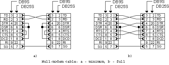
Devices must be connected to physical ports using the so-called null-modem cables. The actual cable wiring depends on device type and configuration. In some cases, two null-modem cables are required while in others two straight or one null-modem and one straight cables are required.
Null-modem cable is a simple cable with two jacks, which connects two RS-232 ports of two DTEs. It connects grounds, RD and TD cross-wise, and other signals are connected according to one of the schemes provided below. The set of transferred channels can be reduced, depending on the flow control being used, in most cases you need as much as only three wires (ground, RD and TD):
A bridge is active only when a monitoring session is running for the bridge.
To create a bridge, either press the Create New Bridge… command on the Devices Tool Window's toolbar or execute the Bridge » Create New Bridge… command.
You need at least two serial devices to create a bridge. The following window appears after you execute the command:
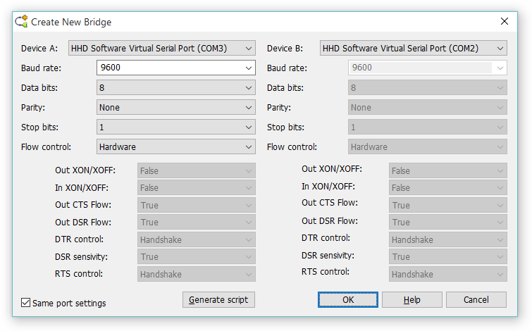
Specify the settings for a new bridge and click the OK button. A window appears that asks for a bridge name. Enter the bridge name and click the OK button.
Once created, a bridge is always present in Devices Tool Window under the “Bridges” subcategory of “Serial” category. You may rename a bridge, change its configuration or remove a bridge using the commands in the Bridge main menu or in bridge's context menu.
In addition, when you start a new monitoring session, Device Monitoring Studio allows you to “temporary” change the bridge configuration only for the duration of this session. “Default” bridge configuration is not affected in this case.
Serial Bridge does not support Capture Filter.
Currently, the following data processing modules are supported for bridges:
Generating Script
Click the Generate script button to generate script that creates a new serial bridge and sets its parameters according to settings in the window.
Multi-Source Support
Serial Bridge does not support multi-source sessions.
Timeout Configuration
TODO
Communications Mode
Serial Bridge Source is somewhat different from other data sources. All data sources carefully capture packets originated in monitored application. In case of serial bridge, Device Monitoring Studio creates a virtual link between two serial devices and forwards data between them. It does not have a priori knowledge of the protocol and therefore cannot issue read and write requests of correct sizes. Device Monitoring Studio uses pre-allocated buffers and default timeout settings and often reads several packets in a single request, or, sometimes reads a single packet in several requests or. This makes protocol binding and data analysis extremely difficult. Moreover, by default, Serial Bridge does not support protocol binding at all.
Device Monitoring Studio allows you to specify the so-called serial communication mode. By choosing communication mode, you give DMS a knowledge of the communication protocol and it starts searching for full protocol packets, or frames in the monitored data stream. It then reorganazies the data stream into correct sequence of read and write requests. When the new data stream reaches configured data visualizers and other data processors, they will deal with perfectly formatted frames, and provide accurate information themselves.
Currently, the following communication modes are supported:
- Generic
- No repackaging occurs. This is a default mode. Protocol binding is not available in this mode. Raw Exporter and Text Exporter visualizers are not available in this mode too.
- PPP
- Serial Bridge Source searches for PPP (Point to Point Protocol) frames in the monitored data stream. In addition to separating the original data stream into individual PPP frames, it also provides character un-escaping.
- One packet in a line
- Includes a large set of ASCII protocols where each packet ends with a CR (0D) character, optionally followed by LF (0A) character. This includes such protocols as AT commands (modems), NMEA (GPS devices), MODBUS (ASCII mode) and so on.
- MODBUS (RTU mode)
- MODBUS RTU mode.
- MODBUS (ASCII mode)
- MODBUS ASCII mode.
PPP frames usually encapsulate a network protocols inside them. Using PPP communication mode and PPP View data visualizer, allows you to automatically decode them.